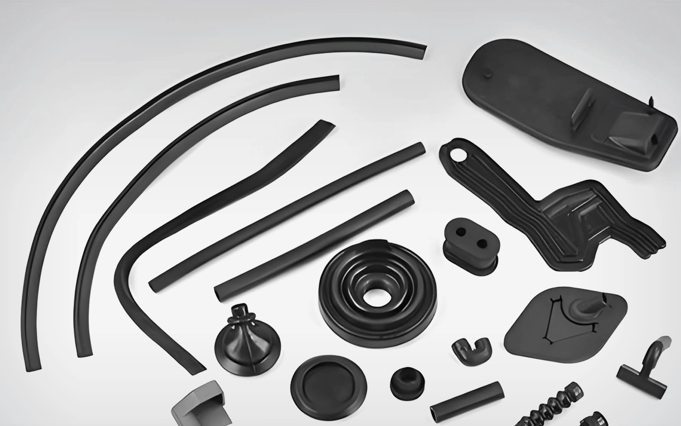
Automotive rubber parts range from sealing strips and corner joints to gaskets, oil seals, bushings, encapsulated glass, and larger molded components. Different compounds and geometries create distinct injection, clamping, handling, and inspection requirements. For these applications, rubber injection molding for automotive industry production consequently requires a platform and cell matched to the part family.
Automotive automation should begin with a part-flow map rather than a list of machines. Feeding, insert placement, injection, curing or cooling, demolding, cleaning, inspection, and transfer should each have a defined handoff, confirmation signal, and safe recovery path. Changeover time, manual intervention, and maintenance access then become part of cell validation instead of afterthoughts. Feeding, insert placement, injection, curing or cooling, demolding, cleaning, and inspection should form one controlled sequence. Faster handling has limited value if material or mold conditions remain unstable.
Map the Part Family and Production Route
General vertical machines can serve many molded rubber products, while servo-hydraulic configurations support TPV, TPE, and flexible modified PVC applications. C-frame presses provide open access for precision joints and inserted parts. Dedicated glass systems and horizontal sealing-ring machines address more specialized workflows.
Dekuma offers RV, RV-Se, RC, glass-encapsulation, and RH platforms for relevant automotive work. These systems differ in material path, clamping arrangement, access, pressure response, and automation options. For sealing-ring work, the separate RH Series should be evaluated against the exact component and compound rather than treated as a general automotive platform. Selection should follow the product rather than a preference for one machine category.
The production route should be mapped before capacity is selected. A corner joint with inserts, an encapsulated glass panel, a sealing ring, and a general molded component follow different loading, material, curing or cooling, demolding, and inspection sequences. The map should identify every manual handoff and every point where the part can be misplaced, stretched, contaminated, or mixed with another batch. Machine capacity can then be calculated around the real route.
Material compatibility requires configuration. Natural rubber, NBR, EPDM, butyl rubber, TPV, TPE, and other compounds have different preparation, injection, curing, and cooling behavior. Trials with the approved formulation and mold provide stronger evidence than a general material list.
Match RV, RV-Se, RC, and RH to the Part Family
An automotive rubber molding process should establish validated ranges for pressure, speed, position, temperature, and time. Sensors and closed-loop controls help the machine repeat those conditions. Inspection data is still needed to show whether the repeated settings produce acceptable parts.
RV should be considered for general molded rubber parts, RV-Se for suitable TPV, TPE, and flexible thermoplastic applications, RC for precision joints or inserted parts requiring open access, and RH for dedicated sealing-ring production. Glass-encapsulation equipment should remain a separate choice for large glazing. The selection record should state why the chosen material path, clamping arrangement, access, and automation plan match the identified part family.
For corner joints and precision seals, accurate dosing helps control flash and incomplete filling. Separated plasticizing and injection, liftable nozzles, cold runners, or FIFO material paths may be valuable on the platforms designed for those functions. Features should not be generalized across unrelated machines.
Mold protection is particularly important when profiles or inserts are loaded. Low-pressure closing, position confirmation, and interlocks can prevent damage before full clamping force is applied. Automated placement should include a clear response to missing, shifted, or duplicated inserts.
Validate Insert Placement, Demolding, and Inspection
Validation should challenge insert placement, mold closing, demolding, transfer, and inspection as one connected sequence. Trials need correctly placed, missing, shifted, and duplicated inserts so that sensors and fault logic can be verified. Warm parts should be supported without distortion, and the cell should retain potentially affected output after an interrupted cycle. Inspection release must be confirmed before the part proceeds downstream.
Automotive parts often require traceability by batch, mold, cavity, compound, and production time. Dekuma’s iSee platform can provide machine status, process data, workflow information, and quality-related records on applicable configurations. Integration scope should match the plant’s production and data systems.
Automated inspection may cover dimensions, surface defects, flash, incomplete edges, or insert presence. The method should be validated with known defect samples and periodic checks. Rejection logic protects downstream work, but recurring defects still require investigation of material, mold, machine, or handling causes.
Changeovers should preserve flexibility. Tool access, stored recipes, identified connections, and repeatable setup checks can be more important than maximum automation in a mixed-product plant. A cell that is fast for one part but difficult to convert may not provide strong overall capacity.
Quality planning should separate cavity-specific defects from general batch variation. Part weight, critical dimensions, surface condition, bond quality, and insert position can be trended against machine data. This comparison makes corrective work more precise and reduces unnecessary adjustments to stable parts of the process.
Design Changeovers, Fault Recovery, and Maintenance
Changeover approval should confirm the mold, compound, inserts, recipe, robot tooling, inspection program, and first-off samples before automatic production resumes. Fault-recovery trials should cover incomplete ejection, missing inserts, sensor disagreement, power interruption, and manual intervention. Preventive maintenance must use the same production baseline so that work on hydraulics, heating, injection components, or automation is followed by defined checks rather than an unrestricted restart.
Long-running programs also need controlled change approval when materials, inserts, molds, or automation are revised. Linking each change to dimensional and functional inspection helps distinguish a true process improvement from a short-term cycle adjustment that may move risk to a later operation.
Commissioning should test normal operation, faults, material changes, mold changes, power recovery, and safe manual intervention. Operators need training in recipes, inspection, cleaning, and alarms, while maintenance teams require deeper instruction on calibration, lubrication, wear, and connected automation.
The strongest automotive rubber molding cell is built around a defined component and verified process window. Machine architecture, material control, handling, data, and maintenance then reinforce one another. This systems approach improves repeatability while keeping the causes of variation visible to production and engineering teams. Stable evidence also supports more disciplined future optimization.


